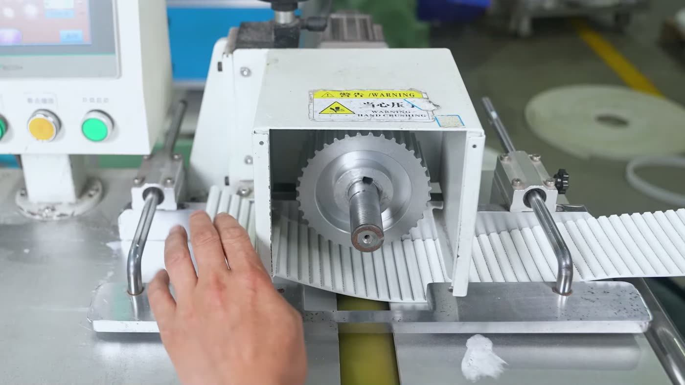
Timing belt drive calculations connect motor speed, pulley tooth counts, belt pitch, center distance, torque, and power. The basic formulas define drive geometry and operating forces. Manufacturer rating tables or design software must then verify belt profile, width, service factor, tension, and pulley limits.
This guide covers an open drive with two external timing pulleys. Diameter and length values refer to the pitch line unless stated otherwise. Keep units consistent and use manufacturer data for final approval.
Key Takeaways
- Speed ratio depends on pulley tooth counts, not pulley outside diameters.
- Pitch diameter equals tooth count multiplied by pitch, divided by π.
- Belt length calculations produce a target that must be matched to a standard tooth count.
- Geometry and force formulas do not replace manufacturer power-rating and tension checks.
Timing Belt Calculation Terms and Symbols
A timing belt calculation begins at the pitch line. The belt pitch line is the neutral axis near the tensile cords, while a pulley pitch circle is the theoretical circle where the belt pitch line meets the pulley. Pitch diameter is therefore larger than pulley outside diameter for normal external pulleys.
| Symbol | Definition | Common Unit |
|---|---|---|
| p | Belt tooth pitch | mm or in |
| z₁, z₂ | Driver and driven pulley tooth counts | teeth |
| zᵦ | Total belt tooth count | teeth |
| d₁, d₂ | Driver and driven pulley pitch diameters | mm or in |
| n₁, n₂ | Driver and driven rotational speeds | rpm |
| i | Transmission ratio | dimensionless |
| C | Shaft center distance | mm or in |
| Lₚ | Belt pitch length | mm or in |
| v | Linear belt speed | m/s or ft/min |
| P | Transmitted power | kW or hp |
| T | Pulley torque | N·m or lb·in |
| Fᵤ | Effective circumferential belt pull | N or lbf |
| β | Arc of contact on a pulley | degrees |
| zₑ | Approximate number of teeth in mesh | teeth |
Subscripts 1 and 2 identify the driver and driven pulley. Some manufacturers use k and g for small and large pulleys, so check each catalog’s symbol definitions.
Pitch length is not the belt’s outside circumference. It is the circumference measured along the pitch line and equals pitch multiplied by belt tooth count. TranBelt’s guide to timing belt pitch measurement explains this distinction and the need to match tooth profile as well as pitch.
Optibelt uses these core quantities alongside service, mesh, speed, fatigue, and length correction factors. That separation is important: geometry can be universal, but load ratings are product-family specific (Optibelt, Technical Manual for Rubber Timing Belt Drives, 2024).
How Do You Calculate Timing Belt Speed Ratio?
For an ideal timing belt drive with no tooth jumping, pulley speed is inversely proportional to tooth count. A larger driven pulley turns more slowly than the driver. Because belt teeth engage positively with pulley grooves, the ratio does not depend on frictional slip during normal operation.
i = n₁ ÷ n₂ = z₂ ÷ z₁ = d₂ ÷ d₁
The driven speed is:
n₂ = n₁ × z₁ ÷ z₂
If a 24-tooth driver runs at 1,500 rpm and turns a 48-tooth driven pulley, the ratio is 48 ÷ 24 = 2. The driven speed is 1,500 × 24 ÷ 48 = 750 rpm. This is a 2:1 speed reduction, and ideal driven torque increases in the inverse direction before efficiency losses.
An open timing belt makes both pulleys rotate in the same direction. A crossed layout reverses direction, but many belts are not intended for reverse bending. Use a manufacturer-approved arrangement when direction must change.
Use tooth count for ratio calculations. Outside diameter lies below the pitch circle and varies with tooth profile. Similar measured diameters can therefore represent different pitch diameters or tooth counts.
How Do You Calculate Pulley Pitch Diameter and Belt Speed?
Pulley pitch diameter is derived from the circumference of the pitch circle. One complete pulley revolution contains a pitch-circle length equal to the number of teeth multiplied by tooth pitch. Dividing that circumference by π gives the pitch diameter.
d = z × p ÷ π
For a 24-tooth pulley with 8 mm pitch, the pitch diameter is 24 × 8 ÷ π = 61.12 mm. A 48-tooth pulley of the same pitch has a pitch diameter of 122.23 mm. These values are theoretical working diameters, not direct caliper measurements across the pulley tooth tips.
Linear belt speed can be calculated from pitch diameter and rotational speed:
v = π × d × n ÷ 60,000
This metric formula uses d in millimeters and n in rpm, producing v in meters per second. Substituting the pitch-diameter formula gives:
v = z × p × n ÷ 60,000
With 24 teeth, 8 mm pitch, and 1,500 rpm, belt speed is 24 × 8 × 1,500 ÷ 60,000 = 4.8 m/s. The result must be the same at both pulleys, so 48 teeth at 750 rpm also gives 4.8 m/s.
For imperial calculations, belt speed in feet per minute equals π multiplied by pitch diameter in inches and rpm, divided by 12. Do not combine millimeters, inches, rpm, and seconds in one formula without explicit conversion.
How Are Power, Torque and Effective Belt Pull Related?
Power, torque, rotational speed, and effective belt pull describe the operating load from different viewpoints. Torque acts at the pulley shaft. Effective pull is the net tangential force needed at the pitch circle to transmit that torque. Neither value is the same as static installation tension.
For power in kilowatts, torque in newton-meters, and speed in rpm:
P = T × n ÷ 9,550
T = 9,550 × P ÷ n
A 2 kW drive at 1,500 rpm applies 9,550 × 2 ÷ 1,500 = 12.73 N·m of driver torque. Ignoring losses, the 750 rpm driven shaft receives approximately 25.47 N·m because the 2:1 speed reduction doubles torque.
Effective belt pull can be calculated from power and linear belt speed:
Fᵤ = 1,000 × P ÷ v
With 2 kW and 4.8 m/s, effective pull is 1,000 × 2 ÷ 4.8 = 416.67 N. The same force follows directly from torque and pitch diameter:
Fᵤ = 2,000 × T ÷ d
This metric form uses torque in N·m and pitch diameter in millimeters. It gives 2,000 × 12.73 ÷ 61.12, again approximately 416.7 N.
Effective pull is the difference between tight-side and slack-side dynamic belt tension. Installation tension is the static pretension applied before operation. It maintains tooth engagement and controls span behavior, but it is not calculated by simply setting it equal to effective pull. Belt construction, span length, acceleration, reversing load, pulley size, and manufacturer tension guidance all matter.
Design power may also exceed motor nameplate power. Synchronous belts transmit startup torque without the overload slip possible in a V-belt drive. Service factors must therefore reflect startup, shock, cyclic duty, braking, and load variation (Gates Corporation, PowerGrip Drive Design Manual, 2020).
How Do You Calculate Timing Belt Length and Center Distance?
For a two-pulley open drive, an approximate pitch length can be calculated from the two pitch diameters and center distance. This formula is accurate for normal layouts but becomes less reliable when pulley diameters are large relative to a short center distance.
Lₚ = 2C + [π ÷ 2 × (d₁ + d₂)] + [(d₂ − d₁)² ÷ (4C)]
Suppose d₁ = 61.12 mm, d₂ = 122.23 mm, and C = 400 mm. The calculated pitch length is approximately 1,090.33 mm. A timing belt cannot have a fractional tooth, so divide the calculated length by pitch:
zᵦ = Lₚ ÷ p
The target tooth count is 1,090.33 ÷ 8 = 136.29 teeth. Select an available integer belt tooth count, such as 136 teeth if that length is offered. The selected pitch length then becomes:
Lₚ,selected = zᵦ × p
A 136-tooth, 8 mm pitch belt has a pitch length of 1,088 mm. Because this differs from the initial calculated length, the actual center distance must be recalculated. First define:
A = Lₚ,selected − [π ÷ 2 × (d₁ + d₂)]
Then solve the same approximate length equation for center distance:
C = [A + √(A² − 2(d₂ − d₁)²)] ÷ 4
For the selected 1,088 mm belt, the recalculated center distance is approximately 398.83 mm. The machine needs enough adjustment to install the belt and apply the specified tension around this nominal position.
Do not round length independently of tooth count. Catalog belts have an exact profile, pitch, tooth count, and width. Check pulley clearance, tensioning travel, and standard length availability.
How Do You Calculate Wrap Angle and Teeth in Mesh?
The smaller pulley normally has the lower wrap angle and fewer teeth sharing the load. For an open two-pulley drive, its approximate arc of contact is:
βsmall = 180° − 2 × sin⁻¹[(d₂ − d₁) ÷ (2C)]
Use pitch diameters, and ensure the calculator is set to degrees. The large pulley angle uses a plus sign instead of a minus sign. When both pulleys have equal pitch diameters, each wrap angle is 180 degrees.
The approximate number of small-pulley teeth in mesh is:
zₑ = zsmall × βsmall ÷ 360°
For the 24-tooth and 48-tooth pulleys at 398.83 mm center distance, the small-pulley wrap angle is approximately 171.2 degrees. Teeth in mesh are therefore 24 × 171.2 ÷ 360 = 11.4 teeth.
This geometric result does not mean all 11.4 teeth carry equal load. Tooth stiffness, pitch error, belt tension, pulley accuracy, and deflection affect load distribution. Manufacturer manuals apply teeth-in-mesh factors or minimum engagement rules to their own belt families. Idlers can increase wrap but also add bending cycles and bearing loads.
Worked Timing Belt Drive Calculation Example
Consider a two-pulley open drive using an 8 mm pitch belt. The driver has 24 teeth and runs at 1,500 rpm. The driven pulley has 48 teeth. Transmitted power is 2 kW, and the preliminary center distance is 400 mm.
| Calculation | Formula | Result |
|---|---|---|
| Speed ratio | i = z₂ ÷ z₁ | 2.00 |
| Driven speed | n₂ = n₁ × z₁ ÷ z₂ | 750 rpm |
| Driver pitch diameter | d₁ = z₁ × p ÷ π | 61.12 mm |
| Driven pitch diameter | d₂ = z₂ × p ÷ π | 122.23 mm |
| Belt speed | v = z₁ × p × n₁ ÷ 60,000 | 4.80 m/s |
| Driver torque | T = 9,550 × P ÷ n₁ | 12.73 N·m |
| Effective pull | Fᵤ = 1,000 × P ÷ v | 416.67 N |
| Calculated pitch length | Two-pulley length formula | 1,090.33 mm |
| Target belt tooth count | zᵦ = Lₚ ÷ p | 136.29 teeth |
| Selected belt | 136 teeth × 8 mm | 1,088 mm |
| Recalculated center distance | Inverse length formula | 398.83 mm |
| Small-pulley wrap | Open-drive wrap formula | 171.2° |
| Approximate teeth in mesh | zₑ = z₁ × β ÷ 360 | 11.4 teeth |
The example establishes geometry and nominal force. It does not prove that any 8 mm belt can transmit 2 kW. Final checks include tooth profile, service factor, rated capacity, belt width, tension, and shaft loads.
Profile compatibility remains essential. HTD 8M, RPP 8M, STD 8M, and proprietary curvilinear profiles may share nominal pitch but use different tooth geometry and ratings. TranBelt’s HTD timing belt guide explains the profile, size, and selection variables for one common family.
Why Formulas Alone Cannot Select the Final Belt
Basic timing belt formulas determine ratio, speed, geometry, and effective pull. Final selection depends on manufacturer test data for the exact tooth profile, belt material, tensile cord, width, pulley size, speed, engagement, service factor, temperature, and duty cycle.
Fluctuating loads, alternating loads, acceleration, and braking require corresponding design factors (Continental, CONTI SYNCHRODRIVE Calculation Documentation, 2025). Optibelt similarly separates nominal power, design power, mesh correction, speed correction, fatigue correction, and belt-length correction.
Use the formulas to create a valid preliminary layout, then enter the duty data into the selected manufacturer’s design method. Verify minimum pulley teeth, maximum speed, belt width, tension, flange arrangement, alignment, adjustment travel, shaft load, resonance, environment, and expected life before releasing the drive for production.
Frequently Asked Questions
Does pulley outside diameter determine timing belt ratio?
No. Timing belt ratio is determined by pulley tooth counts, which correspond to pitch diameters. Outside diameter is measured at the tooth tips and varies with tooth profile. Use i = z₂ ÷ z₁ and verify that both pulleys match the belt’s pitch and tooth geometry.
How do you calculate timing belt pitch length?
For an existing belt, pitch length equals tooth count multiplied by tooth pitch. For a proposed two-pulley drive, estimate length from pitch diameters and center distance, then choose a standard integer tooth count. Recalculate the actual center distance from the selected catalog length.
Is effective belt pull the same as timing belt tension?
No. Effective pull is the net tangential force transmitting torque. Installation tension is static pretension used to maintain engagement and control span behavior. Tight-side and slack-side tensions change during operation, and their difference corresponds to effective pull. Use manufacturer instructions to set installation tension.
How many timing belt teeth should mesh with the small pulley?
Calculate approximate engagement from small-pulley tooth count multiplied by wrap angle, divided by 360 degrees. The acceptable minimum and any rating correction depend on the belt family. Use the manufacturer’s mesh factor or minimum-engagement rule rather than relying on geometry alone.
Should calculated timing belt length be rounded up or down?
Do not use a universal rounding direction. Compare the target with available standard tooth counts, then calculate the resulting center distance for each candidate. Choose the belt that fits adjustment travel, pulley clearance, wrap angle, and tensioning requirements while satisfying the manufacturer’s rating method.
Conclusion
Timing belt drive calculations begin with tooth counts, pitch, speed, and center distance. These inputs determine ratio, pitch diameters, belt speed, approximate pitch length, wrap angle, teeth in mesh, torque, and effective pull.
The result is a preliminary drive layout, not a finished belt selection. Match the calculated length to a standard tooth count, recalculate center distance, and then apply the chosen manufacturer’s ratings, service factors, width rules, tension data, and pulley limits. Keeping pitch-line geometry and product-specific capacity checks separate produces a more reliable design.
Sources
- Optibelt, Technical Manual for Rubber Timing Belt Drives, retrieved 2026-07-20.
- Gates Corporation, PowerGrip Drive Design Manual, retrieved 2026-07-20.
- Continental, CONTI SYNCHRODRIVE Calculation Documentation, retrieved 2026-07-20.
- BRECOflex, Timing Belt and Pulley Glossary of Terms, retrieved 2026-07-20.
- BRECOflex, Timing Belt Drive Definitions and Formulas, retrieved 2026-07-20.