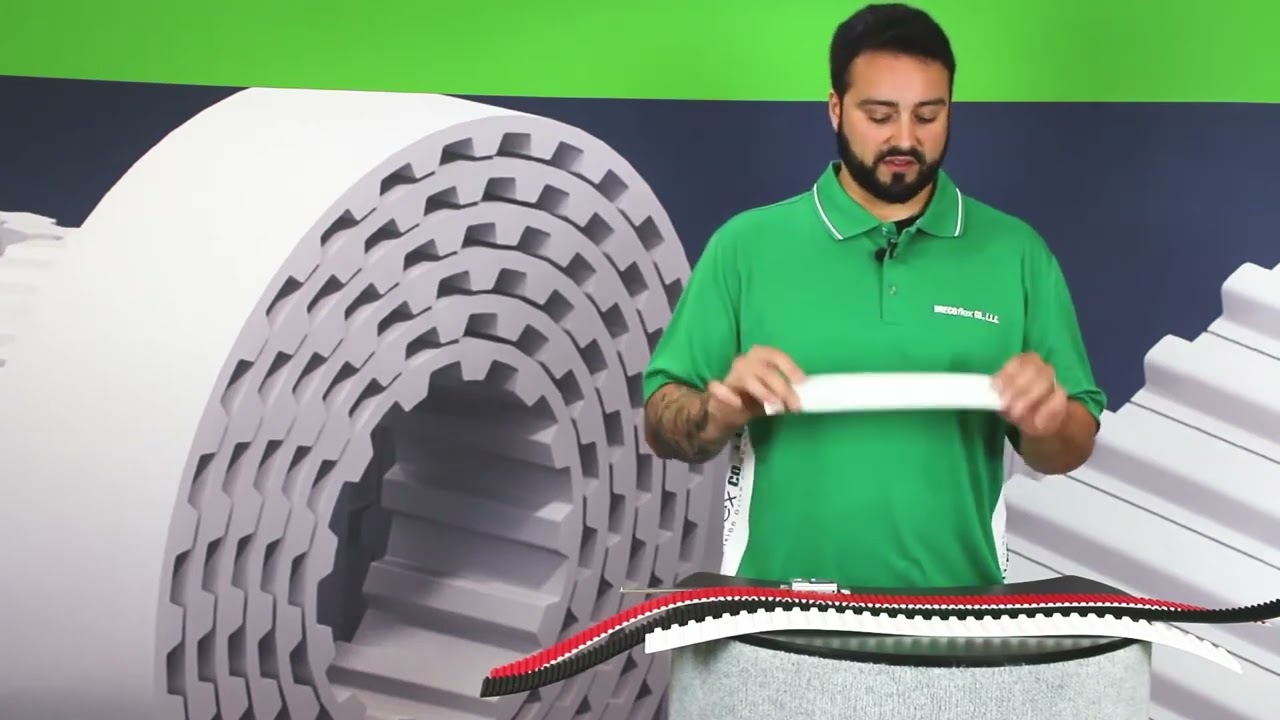
Timing belt pitch is the distance between the centerlines of two adjacent teeth, measured along the belt’s pitch line. It is one of the three essential dimensions used to identify a timing belt, alongside pitch length and width.
Measuring one worn tooth space can produce a misleading result. A more reliable method measures across several tooth intervals, then divides the measured span by the number of intervals. The result must still be matched to a known belt family because equal or similar pitch values do not guarantee a compatible tooth profile.
This guide explains the terms, tools, calculations, common pitch families, and pulley checks needed to identify an industrial timing belt.
Key Takeaways
- Pitch is the center-to-center distance between adjacent belt teeth.
- Measure across several complete intervals rather than one worn tooth gap.
- Ten tooth centers contain nine intervals; eleven centers contain ten intervals.
- Pitch length equals tooth pitch multiplied by the total tooth count.
- Pitch, tooth profile, width, and pulley geometry must all match.
What Is Timing Belt Pitch?
Timing belt pitch is the repeating distance from one tooth centerline to the next, measured at the theoretical pitch line. Gates defines this line as the neutral bending axis of the belt, normally coinciding with the tensile-cord centerline (Gates, Timing Belt Theory, 2026).
The pitch line sits inside the belt, not on its tooth tips. Caliper measurement across several repeated spaces reduces the effects of tooth shape, wear, and jaw placement.
Smaller pitches place more teeth within a given length and often support compact pulleys. Larger pitches are commonly associated with heavier loads. Capacity also depends on width, cords, profile, pulley size, speed, and service factor.
The pulley must share the belt’s pitch. Gates defines pulley pitch along the pitch circle as the arc distance between adjacent groove centerlines. When the belt wraps around the pulley, its pitch line and the pulley pitch circle theoretically coincide.
A 5 mm pitch means adjacent belt tooth centers are 5 mm apart. It does not mean the tooth is 5 mm wide, 5 mm high, or compatible with every pulley carrying a 5 mm label.
How Is Pitch Different from Pitch Length, Width and Tooth Profile?
Pitch describes one repeated tooth interval. Pitch length describes the complete belt circumference along the pitch line. Width is measured across the belt, while the profile defines the tooth’s geometry. All four values affect replacement compatibility.
| Belt Term | What It Means | Typical Unit | Identification Example |
|---|---|---|---|
| Tooth pitch | Distance between adjacent tooth centerlines | mm or inch | 5 mm, 8 mm, 3/8 inch |
| Pitch length | Full circumference measured along the pitch line | mm or inch | 600 mm |
| Tooth count | Number of teeth around the complete belt | Whole number | 120 teeth |
| Belt width | Distance across the belt face | mm or inch | 25 mm |
| Tooth profile | Shape and dimensional standard of each tooth | Family code | T5, AT5, HTD 5M, RPP 5M |
Gates states that pitch length equals pitch multiplied by the number of belt teeth (Gates, Synchronous Belt Identification Chart). A 5 mm belt with 120 teeth therefore has a 600 mm pitch length.
Outside circumference is not pitch length. A tape around the belt back follows a different radius, so its result can differ from the catalog length.
Tooth profile is equally important. T5, AT5, HTD 5M, and RPP 5M all use a nominal 5 mm pitch, but their trapezoidal or curvilinear tooth geometry differs. They should not run on one another’s pulleys unless the manufacturer explicitly approves a conversion.
For an example of how pitch, length, and width appear together in a belt designation, see TranBelt’s XH timing belt size guide.
What Tools Do You Need to Measure Timing Belt Pitch?
Basic identification requires a clean belt, good lighting, a metric and imperial ruler, and calipers. A manufacturer catalog or profile gauge is also useful because the measured pitch must be compared with standard tooth dimensions.
Prepare these tools:
- Digital or vernier calipers with clean jaws
- Steel rule marked in millimeters and inches
- Fine removable marker or chalk
- Magnifying glass or inspection light
- Flat work surface
- Manufacturer profile chart or a known matching pulley
- Tooth-profile gauge when available
Use calipers large enough to span several teeth. A steel rule may be more reliable over a long span when centers are clearly marked.
Remove loose dust without reshaping the teeth. Lay open-ended belting straight and relaxed, and support an endless belt without stretching or sharply bending it.
If the belt is severely worn, measure an undamaged section and inspect the pulley. Pulley grooves can preserve useful profile information when the belt marking and tooth edges are no longer readable.
How Do You Measure Timing Belt Pitch?
The most reliable workshop method measures the same reference point across multiple teeth. Count the intervals, not merely the visible tooth peaks. BRECOFLEX recommends measuring across multiple teeth with calipers to reduce single-tooth error (BRECOFLEX, What Is Timing Belt Pitch? How to Measure and Why It Matters, 2026).
- Record the printed marking. Photograph every visible code before cleaning or handling the belt. The marking may identify pitch, profile, length, width, or construction.
- Choose an undamaged section. Avoid torn teeth, compressed areas, joints, coatings, cleats, and sections permanently curved around a small pulley.
- Select one repeatable reference. Use tooth center to tooth center. On a symmetrical profile, the center can be estimated from matching edges or valleys.
- Mark the first centerline. Place a fine mark at the selected starting tooth center without cutting or scratching the belt.
- Count complete pitch intervals. To measure ten intervals, measure from the first tooth center to the eleventh tooth center. Eleven centers define ten spaces.
- Measure the full span. Keep calipers or the ruler parallel with the belt length. Do not follow a diagonal path across the belt face.
- Divide by the interval count. A 50 mm span across ten intervals gives a 5 mm pitch. A 95.25 mm span across ten intervals gives a 9.525 mm pitch.
- Repeat elsewhere. Check another section and reverse the measuring direction. Similar results increase confidence.
- Compare with standard pitches. Round only after comparing the result with a manufacturer’s dimensional table.
- Identify the tooth profile. Compare tooth shape, depth, angle, root radius, and belt thickness with the suspected family.
Why does the interval count matter? If a ruler touches the centers of ten teeth, it spans only nine center-to-center spaces. Dividing that distance by ten would make the calculated pitch 10% too small. For a ten-pitch measurement, the endpoints must be ten intervals apart.
Use equivalent points in the repeating geometry. Center-to-center measurement is easiest to compare across trapezoidal and curvilinear profiles.
Alternating, self-tracking, double-sided, or special conveying profiles may require the manufacturer’s measurement method and additional dimensions.
How Do You Calculate Pitch Length and Tooth Count?
Pitch length is calculated by multiplying tooth pitch by the total number of teeth. Tooth count is calculated by dividing catalog pitch length by tooth pitch. Gates’ timing-belt theory states that belt length must equal a whole number of belt pitches (Gates, Timing Belt Theory, 2026).
Pitch length = tooth pitch × number of teeth
Number of teeth = pitch length ÷ tooth pitch
For example, a 5 mm belt with 120 teeth has a 600 mm pitch length. An 8 mm belt with 140 teeth has a 1,120 mm pitch length. A classical L belt with a 30-inch pitch length and 3/8-inch pitch has 80 teeth.
Mark the starting tooth and count in groups of ten. Repeat the count before ordering.
If pitch is uncertain, compare calculated lengths with the marking and machine geometry. Do not force them to match an outside-circumference measurement.
Open-ended timing belt is normally specified by profile, pitch, width, construction, and cut length. Its cut length need not contain a whole-number tooth count unless the application or joining method requires complete tooth increments. Endless manufactured belts normally use a complete number of pitches.
What Are the Common Metric and Imperial Timing Belt Pitches?
Common industrial timing belts use both metric and imperial families. The pitch code does not always reveal tooth geometry, so identify the family as well as the numeric spacing.
| Belt Family | Common Pitches | Tooth Form |
|---|---|---|
| Classical MXL, XL, L, H, XH, XXH | 0.080, 0.200, 0.375, 0.500, 0.875, 1.250 in | Trapezoidal |
| Metric T series | T2.5, T5, T10, T20 | Trapezoidal |
| Metric AT series | AT3, AT5, AT10, AT20 | Modified trapezoidal |
| HTD series | 3M, 5M, 8M, 14M, 20M | Curvilinear |
| RPP series | 3M, 5M, 8M, 14M | Curvilinear, profile-specific |
| STD or STPD series | S3M, S5M, S8M, S14M | Curvilinear, profile-specific |
Gates’ identification chart lists classical pitches from MXL at 2.032 mm through XXH at 31.75 mm. It also lists metric T and AT profiles and modern curvilinear families. Availability depends on the manufacturer and material.
The M in 5M or 8M indicates metric spacing, while other letters define the family. HTD 8M and RPP 8M do not automatically share identical geometry.
Trapezoidal T and AT belts also differ despite equal pitch numbers. AT profiles use modified tooth geometry and generally require matching AT pulleys. TranBelt’s RPP timing belt guide provides dimensions for one curvilinear family.
Imperial codes can be less intuitive. XL represents 0.200 inch, L represents 0.375 inch, H represents 0.500 inch, and XH represents 0.875 inch. Use a manufacturer table rather than estimating from the letter name.
How Do You Confirm the Matching Timing Pulley?
Confirm pulley compatibility by tooth count, pitch, groove profile, face width, outside diameter, and flange arrangement. Pitch alone is insufficient. A belt can appear to sit in an incorrect pulley while contacting only tooth tips or groove edges.
First count the pulley grooves. The theoretical pulley pitch diameter is calculated from tooth count and pitch:
Pitch diameter = pulley tooth count × tooth pitch ÷ π
Pitch diameter is larger than the root diameter and usually differs from the measurable outside diameter. Gates explains that the pitch circle coincides with the belt pitch line during mesh. Manufacturer pulley tables provide the relationship between pitch diameter, outside diameter, groove depth, and profile.
Place a short section into a clean, stationary pulley. Teeth should seat uniformly without rocking, tip interference, or progressive mismatch. Never force an uncertain belt into the grooves.
Check pulley width as well. The belt should fit between flanges without edge compression, yet remain guided as the manufacturer intends. Worn grooves, sharp flange damage, packed debris, and eccentric pulleys can make a correct profile appear unsuitable.
For a complete drive, record both pulley tooth counts, center distance, width, shafts, bushings, and running direction. Confirm adequate tooth engagement and minimum pulley diameter.
Frequently Asked Questions
Is timing belt pitch measured from tooth peak to tooth peak?
Pitch is defined centerline to centerline at the internal pitch line. In workshop identification, equivalent points on several tooth peaks or valleys can approximate that spacing. Measure many intervals and compare the average with a manufacturer profile table.
How many teeth should I measure across?
Use at least several intervals, with ten intervals providing a practical span. Measure from the first tooth center to the eleventh center for ten intervals. If you measure ten centers, divide by nine instead.
Can two timing belts have the same pitch but different teeth?
Yes. T5, AT5, HTD 5M, and RPP 5M have a nominal 5 mm pitch but different tooth geometry. Matching pitch does not make their belts and pulleys interchangeable.
Is belt length measured around the outside?
Catalog timing-belt length is normally pitch length measured along the internal pitch line. Outside circumference follows the belt backing and can differ because of belt thickness and cord position.
How do I identify a belt with no readable marking?
Count all teeth, measure pitch across several intervals, measure width and total thickness, compare tooth geometry, and inspect the matching pulley. Confirm the result against a current manufacturer’s dimensional table.
Conclusion
Timing belt pitch is the center-to-center tooth spacing measured along the pitch line. Reliable identification requires measuring several complete intervals, counting the belt teeth, calculating pitch length, and confirming the tooth profile.
Never select a replacement by pitch alone. Match pitch, profile, pitch length, width, construction, and pulley geometry. When measurements remain ambiguous, provide the supplier with the original belt, pulley dimensions, machine information, and clear profile photographs.
Sources
- Gates, Timing Belt Theory, 2026, retrieved 2026-07-16.
- Gates, Synchronous Belt Identification Chart, retrieved 2026-07-16.
- Gates, Industrial Power Transmission Catalog: PowerGrip Timing Belt Identification, retrieved 2026-07-16.
- BRECOFLEX, What Is Timing Belt Pitch? How to Measure and Why It Matters, 2026, retrieved 2026-07-16.
- Continental, Endless Timing Belts and Pulley Dimensions, retrieved 2026-07-16.